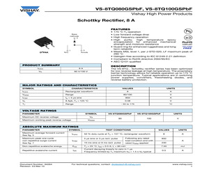
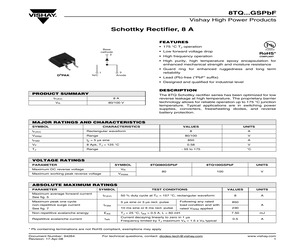
8TQ100GSPbF Vishay High Power Products Schottky Rectifier, 8 A FEATURES * * * * Base cathode 2 * D2PAK 3 Anode 1 N/C * * * * PRODUCT SUMMARY 175 C TJ operation Low forward voltage drop High frequency operation High purity, high temperature epoxy encapsulation for enhanced mechanical strength and moisture resistance Guard ring for enhanced ruggedness and long term reliability Meets MSL level 1, per J-STD-020, LF maximum peak of 260 C Halogen-free according to IEC 61249-2-21 definition Compliant to RoHS directive 2002/95/EC AEC-Q101 qualified DESCRIPTION IF(AV) 8A VR 80 V/100 V The VS-8TQ... Schottky rectifier series has been optimized for low reverse leakage at high temperature. The proprietary barrier technology allows for reliable operation up to 175 C junction temperature. Typical applications are in switching power supplies, converters, freewheeling diodes, and reverse battery protection. MAJOR RATINGS AND CHARACTERISTICS SYMBOL CHARACTERISTICS IF(AV) Rectangular waveform VRRM Range VALUES UNI
 6 Pages, 109 KB, Original
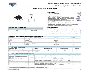
8TQ100GSPbF Vishay High Power Products Schottky Rectifier, 8 A FEATURES * * * * Base cathode 2 * D2PAK 3 Anode 1 N/C * * * * PRODUCT SUMMARY 175 C TJ operation Low forward voltage drop High frequency operation High purity, high temperature epoxy encapsulation for enhanced mechanical strength and moisture resistance Guard ring for enhanced ruggedness and long term reliability Meets MSL level 1, per J-STD-020, LF maximum peak of 260 C Halogen-free according to IEC 61249-2-21 definition Compliant to RoHS directive 2002/95/EC AEC-Q101 qualified DESCRIPTION IF(AV) 8A VR 80 V/100 V The VS-8TQ... Schottky rectifier series has been optimized for low reverse leakage at high temperature. The proprietary barrier technology allows for reliable operation up to 175 C junction temperature. Typical applications are in switching power supplies, converters, freewheeling diodes, and reverse battery protection. MAJOR RATINGS AND CHARACTERISTICS SYMBOL CHARACTERISTICS IF(AV) Rectangular waveform VRRM Range VALUES UNI
 7 Pages, 152 KB, Original
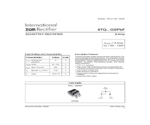
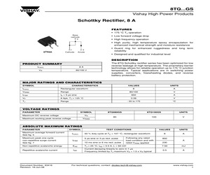
8TQ100GSPbF Vishay High Power Products Schottky Rectifier, 8 A FEATURES * 175 C TJ operation Base cathode 2 * Low forward voltage drop * High frequency operation * High purity, high temperature epoxy encapsulation for enhanced mechanical strength and moisture resistance 3 Anode 1 D2PAK N/C * Guard ring for enhanced ruggedness and long term reliability * Compliant to RoHS directive 2002/95/EC * Halogen-free according to IEC 61249-2-21 definition * Designed and qualified for industrial level DESCRIPTION PRODUCT SUMMARY IF(AV) 8A VR 80 V/100 V The 8TQ... Schottky rectifier series has been optimized for low reverse leakage at high temperature. The proprietary barrier technology allows for reliable operation up to 175 C junction temperature. Typical applications are in switching power supplies, converters, freewheeling diodes, and reverse battery protection. MAJOR RATINGS AND CHARACTERISTICS SYMBOL CHARACTERISTICS VALUES UNITS 8 A 80/100 V tp = 5 s sine 850 A 8 Apk, TJ = 125 C 0.58 V - 55 to 175 C IF(
 6 Pages, 97 KB, Original
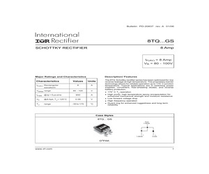
anced ruggedness and long term reliability Lead-Free ("PbF" suffix) Case Styles 8TQ... GSPbF Base Cathode 1 Cathode 3 Anode D2PAK Document Number: 94264 www.vishay.com 1 8TQ...GSPbF Series Bulletin PD-21165 09/06 Voltage Ratings Part number VR 8TQ080GSPbF 8TQ100GSPbF 80 100 Max. DC Reverse Voltage (V) VRWM Max. Working Peak Reverse Voltage (V) Absolute Maximum Ratings Parameters 8TQ Units 8 A IF(AV) Max. Average Forward Current * See Fig. 5 IFSM Max. Peak One Cycle Non-Repetitive 850 Surge Current * See Fig. 7 230 EAS Non-Repetitive Avalanche Energy 7.50 mJ IAR Repetitive Avalanche Current 0.50 A A Conditions 50% duty cycle @ TC = 157 C, rectangular wave form 5s Sine or 3s Rect. pulse 10ms Sine or 6ms Rect. pulse Following any rated load condition and with rated VRRM applied TJ = 25 C, IAS = 0.50 Amps, L = 60 mH Current decaying linearly to zero in 1 sec Frequency limited by TJ max. VA = 1.5 x VR typical Electrical Specifications Parameters VFM 8TQ Max. Forward Voltage Drop (1) * See Fig. 1 IRM M
 8 Pages, 245 KB, Original
nce Low forward voltage drop High frequency operation Guard ring for enhanced ruggedness and long term reliability Case Styles 8TQ... GS Base Cathode 1 Cathode 3 Anode D2PAK 1 8TQ...GS Series Bulletin PD-20837 09/04 Voltage Ratings Part number VR 8TQ080GS 8TQ100GS 80 100 Max. DC Reverse Voltage (V) VRWM Max. Working Peak Reverse Voltage (V) Absolute Maximum Ratings Parameters 8TQ Units 8 A IF(AV) Max. Average Forward Current * See Fig. 5 IFSM Max. Peak One Cycle Non-Repetitive 850 Surge Current * See Fig. 7 230 EAS Non-Repetitive Avalanche Energy 7.50 mJ IAR Repetitive Avalanche Current 0.50 A A Conditions 50% duty cycle @ TC = 157 C, rectangular wave form 5s Sine or 3s Rect. pulse 10ms Sine or 6ms Rect. pulse Following any rated load condition and with rated VRRM applied TJ = 25 C, IAS = 0.50 Amps, L = 60 mH Current decaying linearly to zero in 1 sec Frequency limited by TJ max. VA = 1.5 x VR typical Electrical Specifications Parameters VFM 8TQ Max. Forward Voltage Drop (1) * See Fig. 1 IRM Max.
 7 Pages, 155 KB, Original
peration Guard ring for enhanced ruggedness and long term reliability Case Styles 8TQ... GS Base Cathode 1 Cathode 3 Anode D2PAK Document Number: 93416 www.vishay.com 1 8TQ...GS Series Bulletin PD-20837 rev. A 01/06 Voltage Ratings Part number VR 8TQ080GS 8TQ100GS 80 100 Max. DC Reverse Voltage (V) VRWM Max. Working Peak Reverse Voltage (V) Absolute Maximum Ratings Parameters 8TQ Units 8 A IF(AV) Max. Average Forward Current * See Fig. 5 IFSM Max. Peak One Cycle Non-Repetitive 850 Surge Current * See Fig. 7 230 EAS Non-Repetitive Avalanche Energy 7.50 mJ IAR Repetitive Avalanche Current 0.50 A A Conditions 50% duty cycle @ TC = 157 C, rectangular wave form 5s Sine or 3s Rect. pulse 10ms Sine or 6ms Rect. pulse Following any rated load condition and with rated VRRM applied TJ = 25 C, IAS = 0.50 Amps, L = 60 mH Current decaying linearly to zero in 1 sec Frequency limited by TJ max. VA = 1.5 x VR typical Electrical Specifications Parameters VFM 8TQ Max. Forward Voltage Drop (1) * See Fig. 1 IRM Max.
 8 Pages, 205 KB, Original
tage drop High frequency operation Guard ring for enhanced ruggedness and long term reliability Case Styles 8TQ... GS Base Cathode 1 Cathode 3 Anode D2PAK www.irf.com 1 8TQ...GS Series Bulletin PD-20837 rev. A 01/06 Voltage Ratings Part number VR 8TQ080GS 8TQ100GS 80 100 Max. DC Reverse Voltage (V) VRWM Max. Working Peak Reverse Voltage (V) Absolute Maximum Ratings Parameters 8TQ Units 8 A IF(AV) Max. Average Forward Current * See Fig. 5 IFSM Max. Peak One Cycle Non-Repetitive 850 Surge Current * See Fig. 7 230 EAS Non-Repetitive Avalanche Energy 7.50 mJ IAR Repetitive Avalanche Current 0.50 A A Conditions 50% duty cycle @ TC = 157 C, rectangular wave form 5s Sine or 3s Rect. pulse 10ms Sine or 6ms Rect. pulse Following any rated load condition and with rated VRRM applied TJ = 25 C, IAS = 0.50 Amps, L = 60 mH Current decaying linearly to zero in 1 sec Frequency limited by TJ max. VA = 1.5 x VR typical Electrical Specifications Parameters VFM 8TQ Max. Forward Voltage Drop (1) * See Fig. 1 IRM Max.
 7 Pages, 178 KB, Original
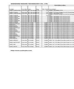
AC 50 package 100V 8A Schottky Discrete Diode in a TO-220AC 50 package 100V 8A Schottky Discrete Diode in a TO-220AC 50 package 0 0 0 0 CH http://www.szshouhe.com ME ME ME ME CH CH ME ME ME ME Email: sales@szshouhe.com SHENZHEN SHOUHE TECHNOLOGY CO., LTD. 8TQ100GSTRL 8TQ100GSTRR TEL: 0755-8380 8450 FAX: 0755-8380 8425 Discrete Schottky Discrete Schottky D2PAK D2PAK 800 100V 8.000A D2PAK 800 100V 8.000A D2PAK 0 0 0 0 0 0 0 ME 0 ME 8TQ100GS Discrete Schottky 8TQ100STRRPBF Discrete Schottky 8TQ100STRLPBF Discrete Schottky D2PAK D2PAK D2PAK 50 100V 8A Schottky Discrete Diode in a D2-Pak package 800 100V 8.000A D2PAK 800 100V 8.000A D2PAK 0 1 1 0 1 1 0 0 0 0 ME 0 ME 0 ME 8TQ100SPBF Discrete Schottky D2PAK 50 100V 8A Schottky Discrete Diode in a D2-Pak package 1 1 0 0 ME 8TQ100STRR Discrete Schottky D2PAK 800 100V 8A Schottky Discrete Diode in a D2-Pak package 0 0 0 0 ME 8TQ100STRL Discrete Schottky D2PAK 800 100V 8A Schottky Discrete Diode in a D2-Pak package 0 0 0 0 ME 8TQ10
 463 Pages, 1366 KB, Original
AND CHARACTERISTICS SYMBOL CHARACTERISTICS IF(AV) Rectangular waveform VRRM Range IFSM tp = 5 s sine VF 8 Apk, TJ = 125 C TJ Range VALUES UNITS 8 A 80/100 V 850 A 0.58 V - 55 to 175 C VOLTAGE RATINGS PARAMETER SYMBOL Maximum DC reverse voltage 8TQ080GSPbF 8TQ100GSPbF UNITS 80 100 V VR Maximum working peak reverse voltage VRWM ABSOLUTE MAXIMUM RATINGS PARAMETER SYMBOL TEST CONDITIONS VALUES UNITS 8 A Maximum average forward current See fig. 5 IF(AV) Maximum peak one cycle non-repetitive surge current See fig. 7 IFSM Non-repetitive avalanche energy EAS TJ = 25 C, IAS = 0.5 A, L = 60 mH 7.50 mJ IAR Current decaying linearly to zero in 1 s Frequency limited by TJ maximum VA = 1.5 x VR typical 0.5 A Repetitive avalanche current 50 % duty cycle at TC = 157 C, rectangular waveform 5 s sine or 3 s rect. pulse 10 ms sine or 6 ms rect. pulse Following any rated load condition and with rated VRRM applied 850 A 230 * Pb containing terminations are not RoHS compliant, exemptions may apply Document Number: 942
 6 Pages, 109 KB, Original
 IF(AV) Rectangular waveform VRRM Range IFSM VF TJ Range VALUES UNITS 8 A 80/100 V tp = 5 s sine 850 A 8 Apk, TJ = 125 C 0.58 V - 55 to 175 C VOLTAGE RATINGS PARAMETER SYMBOL Maximum DC reverse voltage VR Maximum working peak reverse voltage VRWM 8TQ080GS 8TQ100GS UNITS 80 100 V ABSOLUTE MAXIMUM RATINGS PARAMETER SYMBOL TEST CONDITIONS VALUES UNITS 8 A Maximum average forward current See fig. 5 IF(AV) Maximum peak one cycle non-repetitive surge current See fig. 7 IFSM Non-repetitive avalanche energy EAS TJ = 25 C, IAS = 0.5 A, L = 60 mH 7.50 mJ Repetitive avalanche current IAR Current decaying linearly to zero in 1 s Frequency limited by TJ maximum VA = 1.5 x VR typical 0.5 A Document Number: 93416 Revision: 18-Jun-08 50 % duty cycle at TC = 157 C, rectangular waveform 5 s sine or 3 s rect. pulse 10 ms sine or 6 ms rect. pulse Following any rated load condition and with rated VRRM applied For technical questions, contact: diodes-tech@vishay.com 850 A 230 www.vishay.com 1 8TQ...GS Vishay High Powe
 6 Pages, 107 KB, Original
x VF at IF (V) (A) Tj Max (C) SMC 100 0.62 3 175 DO-204AR 60-80-100 0.52 5 175 IF(AV) (A) Device(5) Source(4) 3 30BQ100GPBF I Plastic SMD(1)(3)(9) 5 VS-50SQ100Gx I Plastic Axial(1)(3)(9) 5 VS-50SQ100Gx-M3 I Plastic Axial DO-204AR 60-80-100 0.52 5 175 8 VS-8TQ100GSxPBF I Power Plastic SMD(1)(3)(6) D2PAK 80-100 0.58 8 175 8 VS-8TQ100GPBF I Power Plastic Through Hole(1)(8) TO-220AC 80-100 0.58 8 175 8 VS-8TQ100G-N3 I Power Plastic Through Hole(1)(7) TO-220AC 80-100 0.58 8 175 16 VS-16CTQ100GSxPBF I Power Plastic SMD(2)(3)(6) D2PAK 60-80-100 0.69 8 175 16 VS-16CTQ100GPBF I Power Plastic Through Hole(2)(8) TO-220AB 60-80-100 0.69 8 175 Family Type (1)(3)(7) 16 VS-16CTQ100G-N3 I TO-220AB 60-80-100 0.69 8 175 16 VS-16CTQ100G-1PBF I Power Plastic Through Hole Power Plastic Through Hole(2)(6) TO-262 80-100 0.69 8 175 20 VS-MBRB20100CTGxPBF I Power Plastic SMD(2)(3)(6) D2PAK 100 0.85 10 175 20 VS-MBR20100CTG-1P I Power Plastic Through Hole TO-262 80-100 0.85 10 175 30 VS-30CTQ100GSxPBF I Power Plastic SMD(
 69 Pages, 1992 KB, Original
ctifiers HPS GEN 3.x (Planar Technology) IF(AV) (A) Device(5) Source(4) Package Family Max VF at IF Type V(BR) Range (V) (V) (A) Tj Max (C) 5 50SQ100G I Plastic Axial DO-204AR 60 - 80 - 100 0.52 5 175 3 30BQ100GPBF I Plastic SMD(3) SMC 100 0.62 3 175 8 VS-8TQ100GSPBF I Power Plastic SMD D PAK 80 to 100 0.58 8 175 (2)(3)(6)(7) (3) (1)(3)(6)(7) 2 16 VS-16CTQ100GSPBF I Power Plastic SMD D PAK 60 - 80 - 100 0.69 8 175 20 VS-MBRB20100CTGPBF I Power Plastic SMD(2)(3)(6)(7) D2PAK 100 0.85 10 175 30 VS-30CTQ100GSPBF I Power Plastic SMD D PAK 80 to100 0.82 15 175 40 VS-43CTQ100GSPBF I Power Plastic SMD D PAK 80 to100 0.81 20 175 8 8TQ100GPBF I Power Plastic Through Hole(2)(7) TO-220 60 - 80 - 100 0.58 8 175 16 16CTQ100GPBF I Power Plastic Through Hole(1)(7) TO-220 60 - 80 - 100 0.69 8 175 30 30CTQ100GPBF I Power Plastic Through Hole (1)(7) TO-220 80 to 100 0.82 15 175 60 63CTQ100GPBF I Power Plastic Through Hole(1)(7) TO-220 100 0.83 30 175 40 43CTQ100GPBF I Power Plastic Through Hole(1)(7) TO-220 100 0.8
 64 Pages, 2993 KB, Original
 = TRR = www.vishay.com 20 4. 5. 6. Q101 7. DiodesAmericas@vishay.com DiodesAsia@vishay.comDiodesEurope@vishay.com HPS GEN 3.x IF(AV) (A) (4) 5 50SQ100G 3 30BQ100GPBF 8 IFVF V(BR) (V) (V) (A) (C) DO-204AR 60 - 80 - 100 0.52 5 175 (3) SMC 100 0.62 3 175 VS-8TQ100GSPBF Power D PAK 80 100 0.58 8 175 16 VS-16CTQ100GSPBF (2)(3)(5)(6) Power D PAK 60 - 80 - 100 0.69 8 175 20 VS-MBRB20100CTGPBF Power (2)(3)(5)(6) D2PAK 100 0.85 10 175 30 VS-30CTQ100GSPBF Power D PAK 80 100 0.82 15 175 40 VS-43CTQ100GSPBF Power 8 8TQ100GPBF 16 (3) (1)(3)(5)(6) (2)(3)(5)(6) 2 2 2 D PAK 80 100 0.81 20 175 Power (2)(6) TO-220 60 - 80 - 100 0.58 8 175 16CTQ100GPBF Power TO-220 60 - 80 - 100 0.69 8 175 30 30CTQ100GPBF (1)(6) Power TO-220 80 100 0.82 15 175 60 63CTQ100GPBF Power (1)(6) TO-220 100 0.83 30 175 40 43CTQ100GPBF Power TO-220 100 0.81 20 175 16 16CTQ100G-1PBF Power (1)(5)(6) TO-262 80 100 0.69 8 175 20 MBR20100CTG-1P Power TO-262 80 100 0.85 10 175 30 30CTQ100G-1PBF (1)(5)(6) Power TO-262 80 100 0.82 15 175 40 43CTQ1
 68 Pages, 3846 KB, Original


